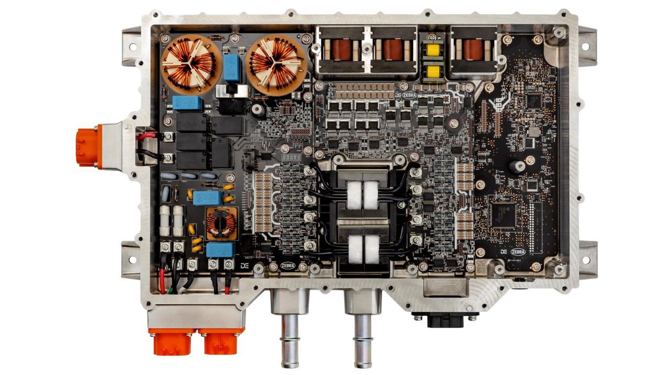
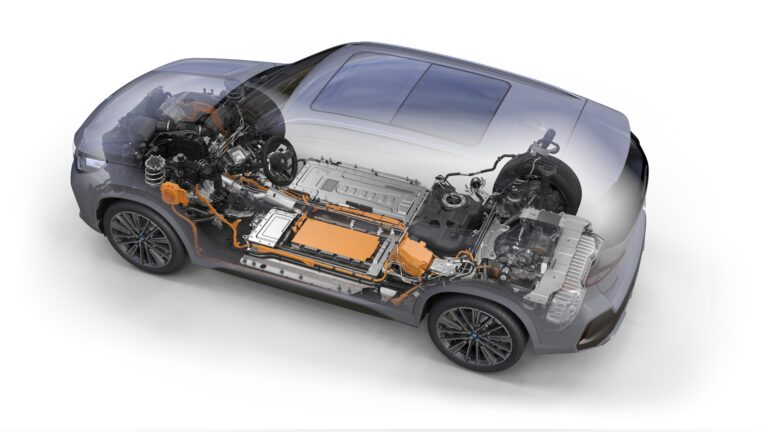
Among the hype surrounding the transition to EVs, with talk of ever-greater battery capacity, increased motor and power electronics efficiency and advances in thermal management, it is easy to overlook the role of onboard chargers (OBCs). The headline charge rate figures that vehicle manufacturers give invariably relate to the performance of dedicated fast chargers, now capable of running at multiple hundreds of kW charge rates. However, the reality is that most EV owners, not to mention those with PHEVs, will normally rely on domestic or workplace charging infrastructure. In the case of domestic chargers, most owners are limited to single-phase power supplies with outputs of up to 11kW, while business premises, more likely to have three-phase power, can currently accommodate up to 22kW chargers (using a 32A supply at 400V in Europe). Hence the need for OBCs.
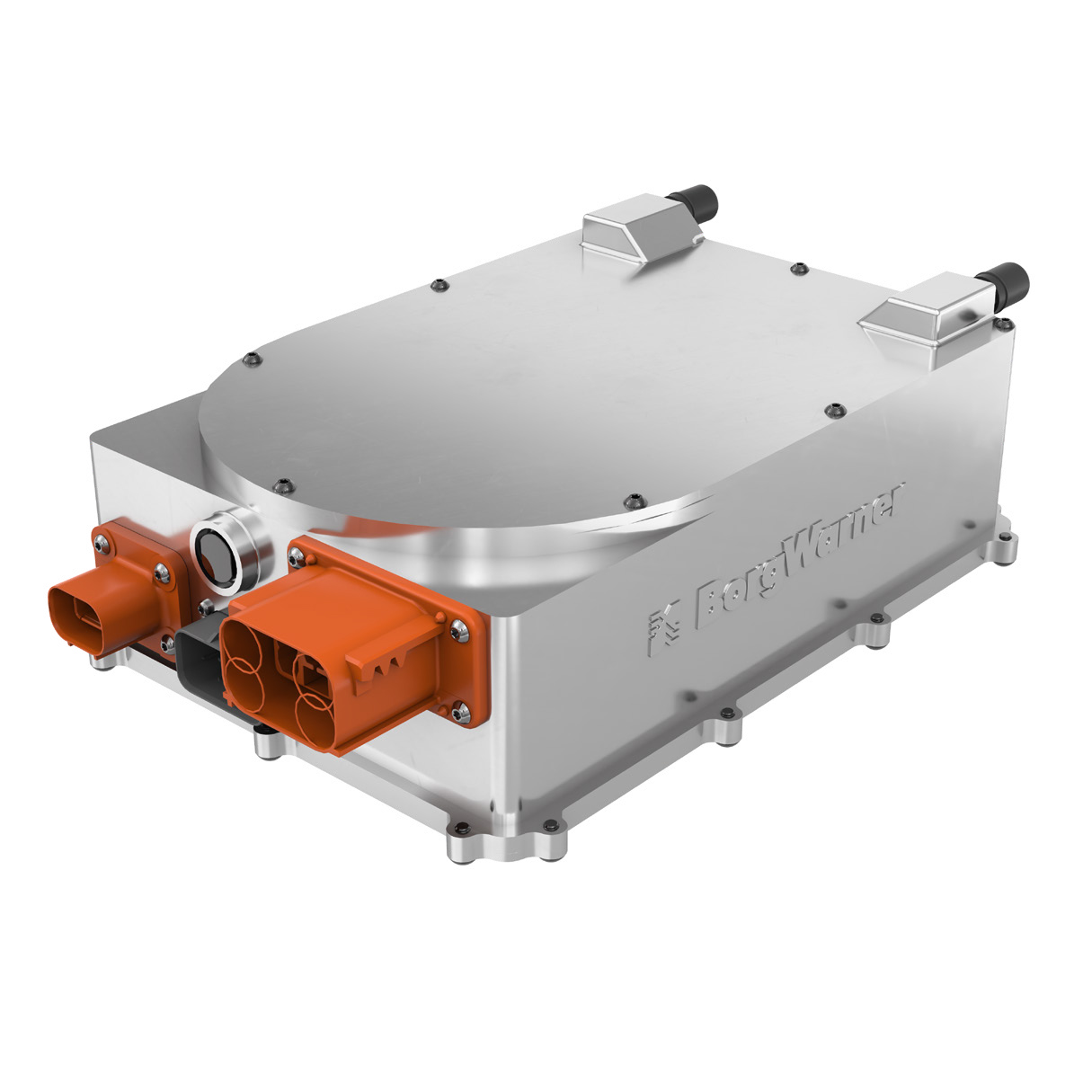
The simplest description of an OBC is a device that converts AC from a wall box to DC, which can be accepted by the vehicle battery (fast chargers are DC, so do not require separate OBC capabilities). In practice, a vehicle’s OBC must balance a variety of competing demands. There are those that apply to every automotive component, such as reducing manufacturing costs and part count alongside ensuring reliability and safety. On top of this are packaging constraints: the OBC must be compact and lightweight to minimize impact on usable space in a vehicle. Above all, an OBC must be efficient to minimize energy use from the grid, and most importantly reduce battery charging times and heat generation. Most vehicle batteries can be charged at a far higher rate than a wall box can provide, so a higher-efficiency OBC will maximize the amount of charge that reaches the battery from the mains source, reducing charge time. With these considerations in mind, it should come as no surprise that OBC producers are offering ever-more power-dense units, with greater efficiency and at lower cost to vehicle manufacturers. So what is the makeup of the most common OBCs currently on the market?

Principles of operation
The majority of OBCs have two key elements: a power factor correction (PFC) stage and a DC-DC converter. The first of these stages is responsible for AC rectification and PFC of the AC flowing from the wall box. A well-designed PFC stage will minimize reactive power while maximizing real power and will convert AC to DC before the DC-DC converter stage. In most automotive applications, the power factor will be in the region of 0.98. Automotive PFCs rely on one of several types of converter, depending on their intended use and price target. Passive power factor correction is possible, but to meet the required power quality needed for battery charging, automotive applications almost exclusively rely on active correction. At one end of the spectrum, low-power, low-cost units tend toward using a boost PFC, a simple AC-DC converter incorporating a switch (normally a silicon MOSFET), diode bridge and inductor. The switching frequency is controlled via a closed-loop system to make the input current sinusoidal and in phase with the input voltage.

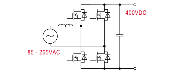
The advantage of boost PFCs is the cost of the components used; however, they are limited to low switching frequencies and voltages. To step up both the power and efficiency levels it is necessary to replace the power-hungry diode bridge with a more efficient device, such as a bridgeless totem-pole PFC. In a conventional bridged boost PFC, four low-frequency diodes, a single high-frequency diode and one high-frequency switch are used. In a totem-pole bridgeless PFC, there are two low-frequency diodes, no high frequency diodes and two high-frequency switches, making for a more efficient device Previously, the use of silicon transistors limited the application of such architectures due to the slow reverse recovery rates of diodes in the MOSFETs, meaning they could be operated only in critical conduction mode (CRM), where the inductor current is allowed to reach zero before the next switching cycle of the MOSFET is started.
However, the advent of silicon carbide (SiC) MOSFETs and gallium nitride-based (GaN) transistors has made totem-pole PFCs applicable in higher-power applications. Unlike boost PFCs, they are capable of continuous conduction mode (CCM) operation, where the MOSFET switches before the inductor is completely discharged and its current never reaches zero. The two main advantages of the totem-pole PFC are bidirectional operation and a reduction in conduction losses. Moving to higher-power OBCs, either 11kW single-phase or 22kW three-phase, it is possible to use several lower-power units in parallel; however, bespoke architectures can net higher power densities.
For example, a Vienna rectifier can be used for power correction. This is a pulse width modulation rectifier with a number of advantages over the previously described devices, including the ability to operate in CCM, as well as a three-level structure that means the voltage seen by each device within the rectifier is only half that of the output voltage – a useful factor when dealing with 800V systems. Again, SiC MOSFETs are the current favored option for providing high switching speeds and low losses in these devices, though GaN or GaN/SiC combination systems are also now available.
 DC-DC
DC-DC
With the PFC taken care of and a regulated DC output available, it is then necessary to step this up to the voltage required by the battery system, normally 400V but increasingly 800V and upward. This is achieved by a DC-DC converter that is electrically isolated from the AC-DC stage. In the past, the DC-DC converter and PFC would be separate components, but the quest for packaging efficiency now sees the two stages more often than not integrated within a single unit, sharing the same housing and location in a vehicle. For low-power, low-cost applications, a half-bridge LLC DC-DC converter can be used. This is a type of resonant power converter that uses a network of inductors and capacitors to convert a DC input voltage into a square wave, which is then fed into a transformer to scale the voltage to the required level.
LLC converters can achieve high efficiency levels while also having low EMI, an important consideration in vehicles that are housing increasing numbers of electronic devices and onboard processing power. For 400V applications and upward, a full-bridge LLC will often be used for unidirectional changing, with the higher operating voltage helping to reduce losses. A full-bridge design can be deployed right up to 22kW; however, the choice facing engineers is whether to use Si- or SiC-based MOSFETs, or GaN, which becomes a trade-off between cost and efficiency.
While it is entirely possible to build a 22kW OBC using purely Si-based components, it is not ideal, and a more efficient and power-dense unit can be created using SiC or GaN components. For very low-power solutions (under 2kW), where cost is a prime consideration, Si remains a firm favorite, but even for mid-power chargers, SiC is becoming the go-to solution for both elements of an OBC. For example, a mid-power system up to around 7kW could include SiC diodes in the PFC stage, netting a useful gain in efficiency, while still relying on Si for the DC-DC converter, keeping costs low at the expense of some efficiency. Conversely, SiC diodes and MOSFETs could be deployed across both stages, a higher-cost but more efficient option.
At higher power levels, 11kW and up, not only does SiC provide better switching speed and lower losses for all elements, it also results in a lower overall system cost than Si. An LLC converter is not applicable for bidirectional charging, due to the voltage gain of these devices being limited when in reverse operation mode. The solution is to use a bidirectional CLLC converter, which has a symmetrical resonance tank (the main element of an LC circuit made up of inductors and capacitors that oscillate at a specific frequency) enabling a wide output voltage range and good efficiency in both charge and discharge modes. Another option is to use a dual active bridge (DAB), which is a bidirectional converter using identical primary and secondary side full bridges, a high-frequency transformer, an inductor and DC-link capacitors. Both of these solutions can make good use of SiC transistors to maximize efficiency and energy density.
Future trends
Advances in the power density of OBCs in recent years have netted some impressive gains, and the best commercially available units have jumped from under 2kW/l to around 3.5kW/l. This figure is set to grow in the near term as increasingly integrated products hit the market. The adoption of bidirectional charging, where V2G (vehicle to grid) power flow is enabled, is also likely to accelerate, helping pave the way for smarter operation of electrical grids and increased overall efficiency of the EV ecosystem. There are also many developments underway in areas such as single-stage chargers, which negate the need for separate conversion and DC-DC converter stages, promising further packaging advantages. Another avenue of development is the use of a vehicle’s traction motor and inverter as a charging system – an integrated battery charger topology. With the inverter already a DC-AC converter, the electric motor is used as the inductor for the boost PFC, entirely removing the need for a standalone charger. This approach is not without challenges – for example, the need to design motor windings with this use in mind. There are also issues surrounding isolation between the vehicle and grid, and ensuring that no tractive effort is produced by the motor during charging. However, Renault has deployed an integrated charger in its Zoe, capable of charging at up to 43kW, while Tier 1 supplier Valeo has also marketed an integrated inverter charger unit.


